Product Overview
SimLab is a process oriented, feature based finite element modeling software that enables you to model the engineering behavior of complex assemblies fast and accurate.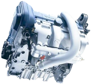
SimLab automates simulation-modeling tasks to reduce errors and to save time that is usually spent in manually creating finite element models and interpreting results.
SimLab is a vertical application platform to capture simulation processes and to automate them.
When the process is defined it can be run again and again giving quick results with constant quality.
Through consequent automation of the modeling process it is possible to achieve very short modeling cycles as examples from customer show.
-
1 day for engine stress modeling
-
1 day for a NVH model of an engine
-
4 hours to model a brake system
The process of finite element modeling of complex assembly consists of several steps: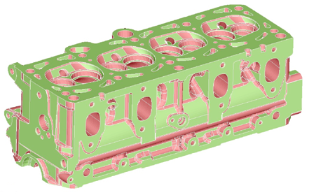
-
Geometry creation and cleanup
-
Meshing
-
Assembly
-
Applying loads and boundary conditions
For every of these steps SimLab provides advanced and comprehensive functionality to accelerate the process.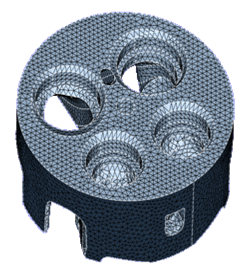
Geometry
SimLab has routines to directly access the native geometry of the following CAD systems:
-
CATIA V5
-
Pro/Engineer
-
For CATIA and Pro/Engineer SimLab SimLab can access the geometry across platforms, Linux (CAE) – Windows (CAD) including model features, parameters and topology information.
-
UG using Parasolid
-
Other Parasolid based CAD systems like SolidsWorks, SolidEdge, and so on.
-
IDEAS via IDI or Parasolid xmt_txt data format.
Geometry handling - Benefits:
-
Accurate representation of the geometry
-
Meshing of the CAD model is guaranteed by the various tools for mesh clean-up
-
Quick identification of relevant geometry by using the features of the CAD model.
-
Flexibility regarding the operating system for CAE

-
Availability of parameters for DoE
Meshing
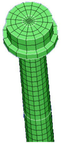
SimLab takes the features from the CAD model like fillets and cylinders and transfers them to the finite element model. Thus these features can be used in a later step in the process whithout the need to access the original CAD geometry again.
SimLab provides all common general meshing capabilities:
-
Generation of 1D and 2D elements
-
Surface meshing with triangular or quadrangular elements
-
Volume meshing with tetrahedral or hexahedral elements
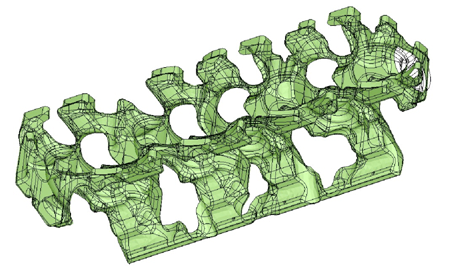
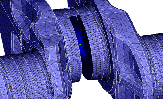
The recommended approach for meshing in SimLab is to create first a high quality surface mesh for every component of an assembly. Then use this surface mesh to generate a volume mesh keeping the quality of the mesh on the surface.
To achieve a fast meshing SimLab has many tools. Some of them are listed below:
-
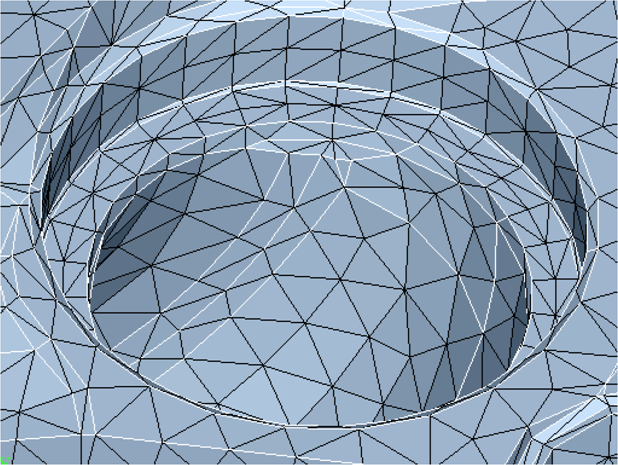
Features like cylinders, fillets, contact surfaces are being explicitly preserved in order to get a good surface mesh in these areas.
-
Mesh specification at e.g. fillets by using automatic fillet dectection.
Meshing - Benefits:
-
Quick and automatic identification and meshing of relevant areas of a component
-
High quality surface mesh by using mesh specifications
-
Good respresentation of thin walls
-
Constant mesh quality for simimlar components by re-using defined mesh specifications
The finite element mesh has to meet the specific requirements of the different analysis types.
SimLab therefore offers features to generate application specific finite element meshes for durability, NVH, acoustics, life prediction, CFD and 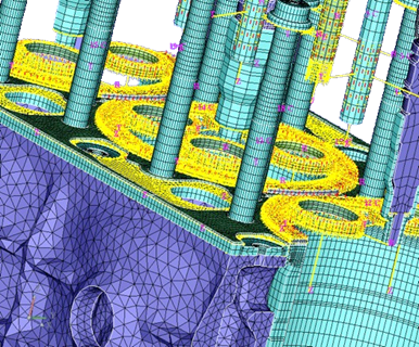 more.
more.
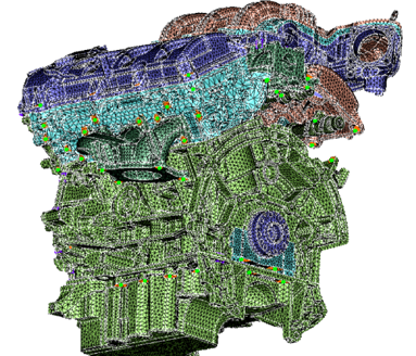
Assembly
Increasingly, the analysis of an assembly, a system of components, is required.
From experience it is very time consuming to position the components in the assembly, to determine contact areas, to make nodes coincident and to connect the individual parts.
SimLab provides several simple and robust tools making it easy to generate an assembly of components for finite element analysis. These tools can reduce the time spent in the assembly by a factor of 5 or more.
These tools comprise amongst others:
-
Functionality for easy and fast positioning of components in an assembly
-
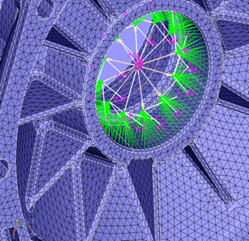
Automatic identification of contact surfaces between components
-
Automatic re-meshing in the contact areas to get coincident nodes
-
Library of common connecting elements
-
Automated joining techniques via templates
-
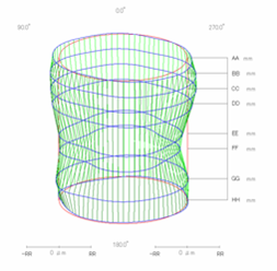
Special tools for gasket modeling
Assembly - Benefits:
-
Fast positioning and replacement of components of an assembly
-
Easy and time saving connection of the individual parts
Loads and Boundary Conditions
As the model sizes become larger and larger with millions of nodes and elements, it is no longer practical to refer to individual nodes and elements in defining the loads and boundary conditions.
SimLab offers features for a widely automatic assigment of loads and boundary conditions by using templates.
The process oriented features of SimLab include:
-
Automated Bolt modeling (Pre-tension, NVH bolts)
-
Applying distributed bearing reactions
-
Conversion of results from a fine to a coarse mesh and from a coarse to a fine mesh

-
Positioning of spatially displaced result fields onto the model
Postprocessing and Solvers
SimLab supports the most popular finite element solvers (Nastran, Permas, Abaqus, Ansys, Beasy) and result displays.
In addition life prediction with FE-SAFE and crack growth analysis with BEASY can be performed from within SimLab.